Anybus Studio guide
Configuration workflow
Before you begin
Ensure you have access to an Anybus Studio account. See Create your Anybus Studio account.
Plan configuration
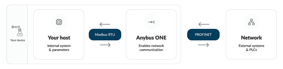 |
Before you start the configuration process, decide how Anybus ONE should operate within the host system and the industrial network. Gather the information required to support this setup.
This preparation helps streamline the configuration and reduces interruptions.
See also Plan your configuration.
Configure host interface
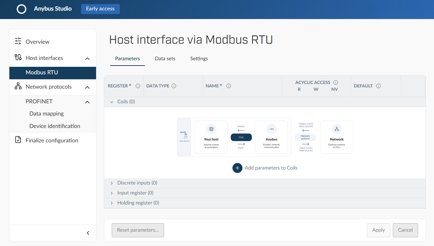 |
On the Host interface via Modbus RTU page, you configure the internal communication protocol between Anybus ONE and the host application.
The Modbus RTU interface enables bidirectional data exchange between the industrial network and the host application via Anybus ONE.
Both sides can read and write parameters, control functions, and share data.
Configure the Modbus RTU interface:
Parameters: Enable communication between your host system and Anybus ONE.
Define the parameters that will be mapped to the Modbus registers.
Data sets: Enable cyclic I/O communication between the Modbus RTU interface and the industrial network.
Create one or more data set and group the relevant parameters into these sets.
Settings: Configure the communication behavior, data format, and error handling for the Modbus RTU interface.
See Configure Modbus RTU.
Configure network protocol
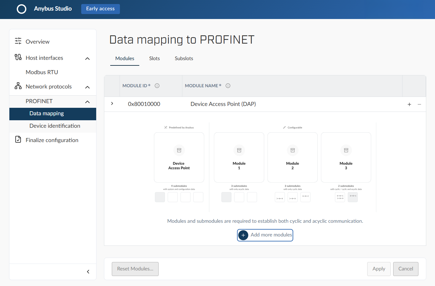 |
On the Data mapping to PROFINET page, you configure the external PROFINET protocol to enable bidirectional transfer of parameters and data sets between the host interface and the industrial network, via Anybus ONE.
The external systems and PLCs can exchange data seamlessly with your host's internal systems.
Configure the PROFINET interface:
Modules: Define the modules and submodules that represent the functional units of your PROFINET device.
Add one or more module. Each module must contain at least one submodule.
Slot and Subslots: Define where each component appears in the PROFINET device hierarchy.
Assign modules and submodules to specific slot and subslot positions.
Identification: Configure device identification settings.
The identification information uniquely describes the device on the industrial network.
See also Configure PROFINET.
Finalize configuration
Important
Configuration data is stored in browser local storage only. If the browser data is cleared, the configuration is lost.
Download and save the configuration files locally to retain the configuration for future use.
Download files
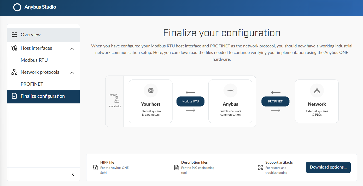
On the Finalize page, download:
HIFF file: Configuration HIFF file to install on Anybus ONE System on Module (SoM).
Anybus ONE Signing tool: Windows tool for signing and verifying HIFF files for installation.
Device description file: File used by external controllers, such as PLCs, to integrate the device in the industrial network. For PROFINET, this is a GSDML file.
Support artifacts: Includes JSON files for full configuration backup and files for troubleshooting and support.
Sign the configuration HIFF file
Sign the HIFF files in the Anybus ONE Signing tool before installation on Anybus ONE System on Module (SoM).
See also Sign configuration files.