Configure PROFINET Master Simulator
Configure the PROFINET Master Simulator to communicate with the Anybus ONE Evaluation Board.
Before You Begin
Ensure the following:
The computer network interface and the Evaluation Board belong to the same IP subnet.
The HMS PROFINET Master Simulator is installed and licensed.
The Evaluation Board is powered and connected to the computer.
The Modbus RTU slave simulator is running and communicating with the Evaluation Board. See also Configure Modbus RTU Slave Simulator.
You have a GSDML file associated with your Anybus ONE SoM that contains the configured PROFINET device description.
To download the GSDML file for the default configuration, see Example configuration: download and use.
Procedure
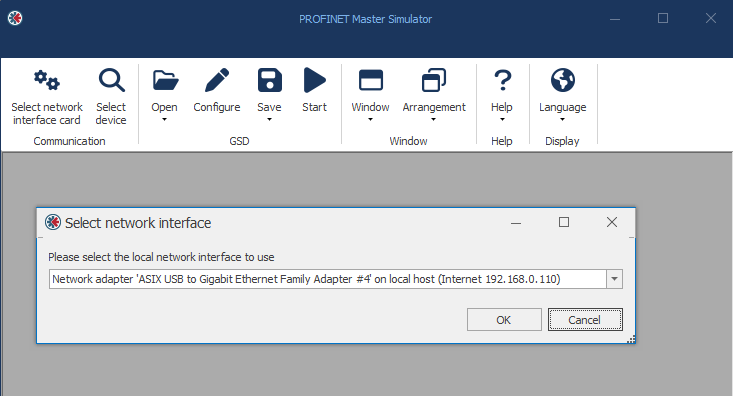 |
Start the HMS PROFINET Master simulator.
Click Select network interface card.
Select the network interface card connected to the Evaluation Board.
If the PC has only one network interface, it is selected automatically.
Important
clears the device name and IP configuration.
Tip
Use to locate the Evaluation Board. The Network Status (NS) and Modbus Status (MS) LEDs blink green at 1 Hz.
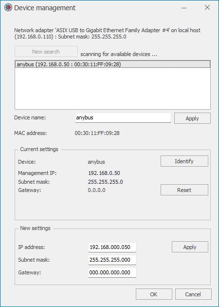 |
Click Select device to scan for connected PROFINET devices.
Select the Evaluation Board.
Configure the following network settings as needed:
Device name: Enter a unique name of the Evaluation Board (for example, “evb1”).
IP settings: Network IP settings of the Evaluation Board used for Ethernet communication.
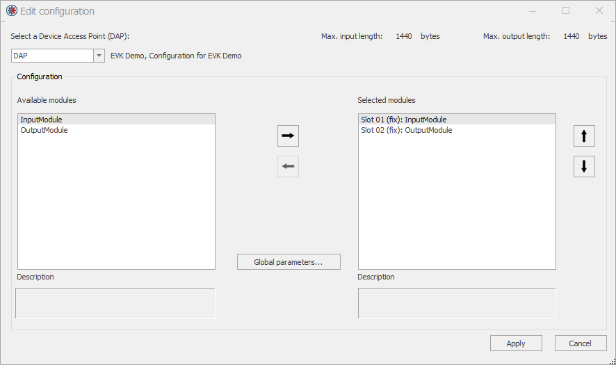 |
Click Open.
Select the GSDML file.
The configured PROFINET modules are displayed.
Review and adjust the configured PROFINET modules:
Modules configured as Fixed in are automatically populated.
Modules configured as Allowed in must be moved from Available modules to Selected modules.
Click Apply.
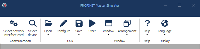
Click Start.
Wait for communication to establish.
Result
Communication is established when:
The status banner in the simulator turns green.
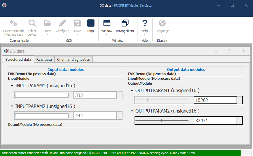 Figure 20. PROFINET communication active
The Network Status (NS) LED on the Evaluation Board turns steady green.
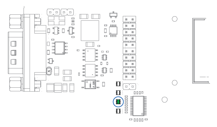 Figure 21. Evaluation Board Network Status (NS) LED