Parameter definition
Parameters define the data values exchanged between your device application and the Modbus RTU host interface.
Each parameter represents a single logical value in your application and is mapped to a Modbus register by assigning:
Register type
Register address
Data type
Acyclic access
Default value
What parameters represent
On the Modbus RTU interface, parameters form the connection between application data and the Modbus register model.
Typical parameters include setpoints, measurements, counters, and status indicators.
Well‑defined parameters make the register map easier to understand and help reduce configuration errors.
Modbus registers use addresses in the range 0x0000–0xFFFF (0–65 535).
Each Modbus register type has its own address range with the same numeric limits.
The register types differ in how data is accessed and how values are interpreted.
Register types
Register types are identified by Modbus register prefixes and their access characteristics.
Assign addresses that are unique within each register type.
Prefix | Register type | Access | Data size |
|---|---|---|---|
0x | Coils | Read/write | 1 bit |
1x | Discrete inputs | Read only | 1 bit |
3x | Input registers | Read only | 16 bit |
4x | Holding registers | Read/write | 16 bit |
Note
If the Modbus system uses 1‑based addressing (0x0001–0x10000 / 1–65 536), subtract one before entering the address in Anybus Studio.
The data type defines how a parameter value is interpreted and how it is stored in the Modbus register model.
The size of the data type determines how many Modbus registers the parameter occupies:
Holding registers and Input registers are 16 bits
Coils and Discrete inputs are 1 bit
Parameters larger than one register span multiple Modbus registers and use consecutive register addresses.
Holding registers and Input registers support data types with sizes that are multiples of 16 bits.
Coils and Discrete inputs support all data types of any size.
Examples
UINT16 - uses 1 register
UINT32 - uses 2 registers
FLOAT64 - uses 4 registers
Acyclic access defines how the Anybus SoM may read from or write to a parameter.
Access type | Description |
|---|---|
R | Read – The Anybus SoM may read the value |
W | Write – The Anybus SoM may write the value |
R/W | Read and write – Both read and write are allowed |
NV | Non‑volatile – The value is stored across power cycles |
Access rules by register type
Access permissions depend on the register type:
Coils and Holding registers support read and write access
Input registers and Discrete inputs are read only
Read and write behavior
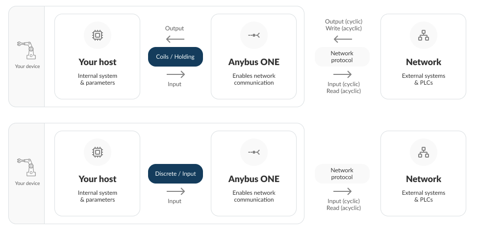
Input registers and Discrete inputs represent values produced by the application and are defined as read‑only by the Modbus specification.
Coils and Holding registers are intended for writable commands and configuration values.
Data access when exposed to external industrial network interfaces depends on the register type:
Input registers and Discrete inputs always provide read‑only access
Coils and Holding registers support read and optional write access
Specifies the value used in offline mode and during device startup.
For non-volatile (NV) parameters, the default value is also applied based on the configured offline action and after a factory reset.