Configure PROFINET
Configure the PROFINET device model for your device.
This configuration defines the device structure used to generate the GSDML file.
 |
Before you begin
Ensure you have:
Configured the Modbus RTU host interface, which defines the PROFINET I/O data.
See also Configure Modbus RTU.
The list of functional units, (modules, that represent the device.
The planned slot and subslot layout; including any fixed or required positions.
Defined cyclic and acyclic parameters; names, indexes, data types, default values, access rights.
See also Plan your configuration.
Configuration order
Configure PROFINET in the following order. Each step depends on the previous one:
Modules
Slots
Subslots
Identification
Define modules
Modules represent the functional parts of your device exposed to the PROFINET network.
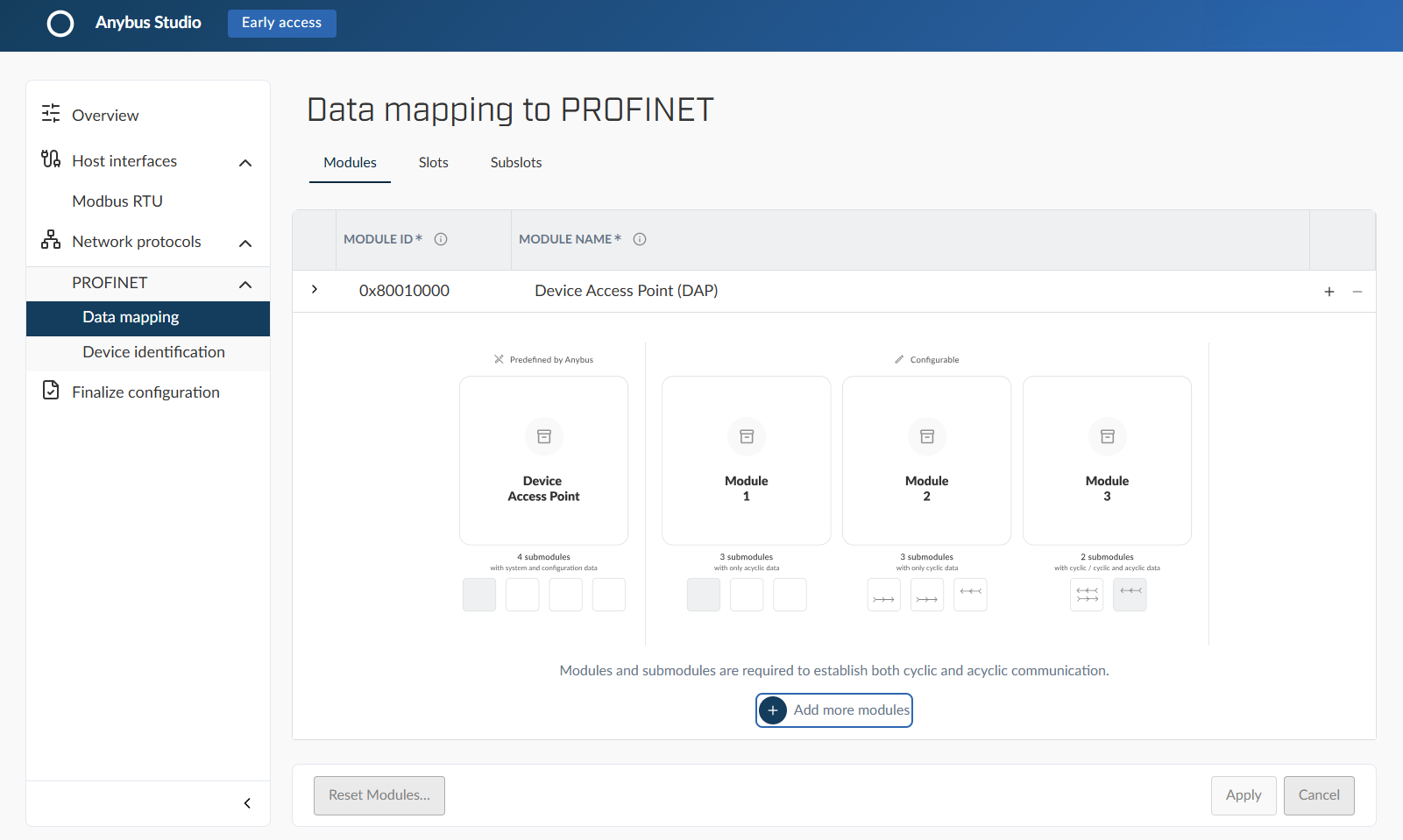
Define modules and submodules in the Modules tab.
Module definition
For each module, define:
Module ID: User‑defined numerical identifier; must be unique across all modules
Module name: A descriptive name, visible in engineering tools
Submodules
Submodules define how data, parameters, or diagnostics are exposed within a module.
For each submodule, define:
Submodule ID: User-defined numerical identifier; must be unique within the module
Submodule name: A descriptive name, visible in engineering tools
Cyclic input data: Used when the submodule receives data from the controller
Cyclic output data: Used when the submodule sends data to the controller
Virtual status: Used when the submodule represents configuration, diagnostics, or logical functionality without cyclic I/O data
Module rules
The following rules apply to modules and submodules:
Module IDs must be unique
Submodule IDs must be unique within a module
Each module must contain at least one submodule
The last remaining submodule in a module cannot be removed
Assign modules to slots
Assign modules to slots in the Slots tab to define their position in the PROFINET device structure.
Slots determine how the controller addresses each module in the GSDML.
Slot definition
For each slot, define:
Slot number: Auto‑generated logical position of the module in the PROFINET device structure; used by the controller to address the module
Slot name: A descriptive name, visible in engineering tools
Module: Assign a Module to the Slot
Plugging rule: Allowed in, Fixed in, or Used in
Slots rules
The following rules apply to slot configuration:
Each module can be assigned to only one slot
Slot numbers must be unique
Slot 0x00 is reserved for the Device Access Point (DAP)
Assign submodules to subslots
Assign submodules to subslots in the Subslots tab to enable cyclic and acyclic data access.
Subslots define where submodules appear within a module.
Subslot definition
For each subslot, define:
Subslot number: Auto‑generated logical position of the submodule within the module; Used by the controller to address cyclic and acyclic data
Subslot name: A descriptive name, visible in engineering tools
Submodules : Assign one or more submodules
Plugging rule (Optional): Allowed in, Fixed in, or Used in; Required when the subslot contains mandatory or virtual submodules
Subslots rules
Submodule assignment is exclusive
Subslot numbers must be unique within a slot
Mandatory submodules must always be present
Define identification data
Define the device identification data on the Identification page.
Identification data defines how your device is described on the PROFINET network, including:
Device type
Supported functions
Structural information
See also Parameter definition.
Validate the configuration
Important
The device model generates the GSDML used by the controller.
If the device model is incomplete or inconsistent, data exchange will not start at controller startup.
For GSDML generation to succeed, ensure the following:
All required modules and submodules are present and assigned.
Slot and subslot numbers are unique and valid.
Acyclic records are correctly indexed and typed.
No configuration items are left incomplete.
Result
A valid interface configuration ready for GSDML generation.