Network and Modules status LED indicators
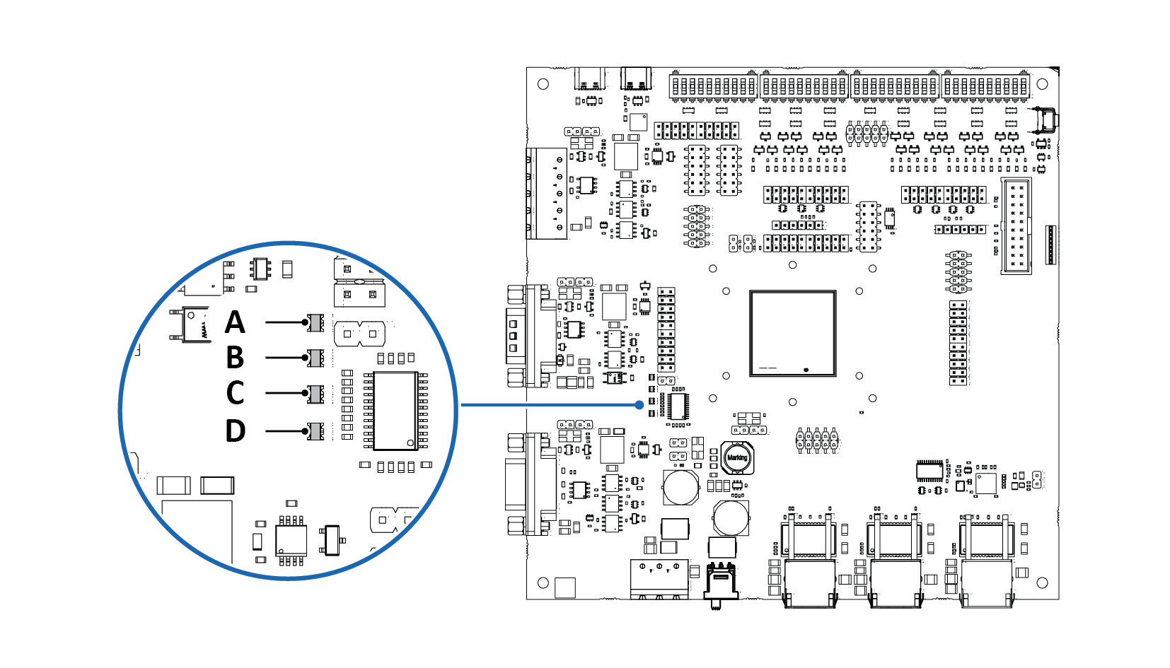 |
Position | LED | Color | State | Description |
|---|---|---|---|---|
A | - | - | - | Reserved for future features |
B | - | - | - | Reserved for future features |
C | Network Status (NS) | Off | - | No IP address configured or no power |
Red | Steady ON | Fatal error, MS also steady red | ||
Red | Steady ON | Duplicate IP address | ||
Red | Blinking 1 Hz | IO connection timeout | ||
Green | Blinking 1 Hz | Identification signal active (DCP Control/Signal), MS also blinking green | ||
Green | Blinking 1 Hz | IP address configured, no IO connection, or IO connection in a bad state | ||
Green | Steady ON | IP address configured and IO connection established (at least one IO channel open, all IO channels OK) | ||
D | Module Status (MS) | Off | - | No power |
Red | Steady ON | Fatal error, NS also steady red | ||
Red | Steady ON | Configuration error | ||
Red | Blinking 1 Hz | Internal error | ||
Green | Blinking 1 Hz | Identification signal active (DCP Control/Signal), NS also blinking green | ||
Green | Steady ON | Module healthy and configured |
Power-up test sequence (initialization): After power-up, before normal indication begins, the MS and NS indicators will perform a power-up test sequence.