Use diagnostic interface for debug
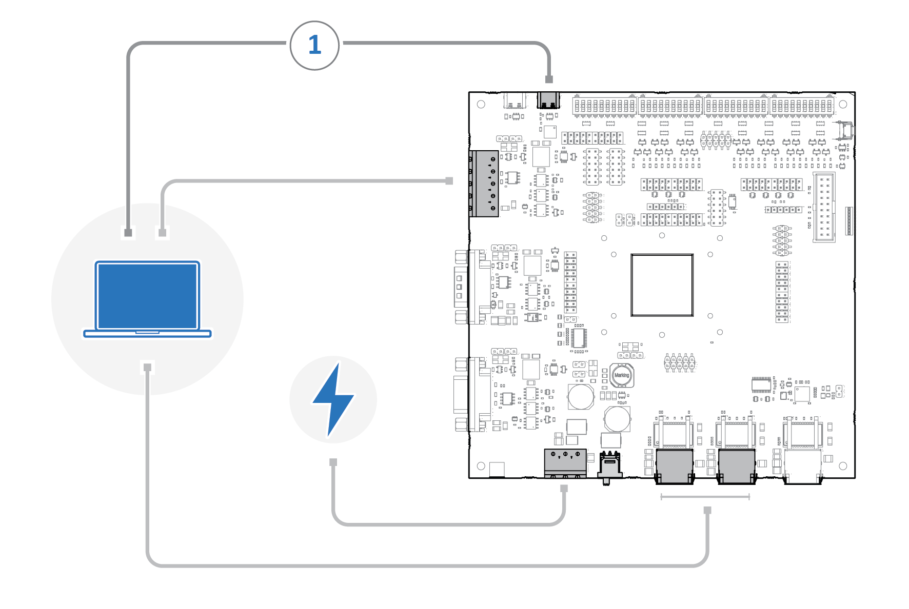
Diagnostic output is available on UART1, routed to the USB‑C interface on the Evaluation Board.
 |
Before you begin
Ensure the Evaluation Board is connected to either available Ethernet ports and the Modbus RTU 5‑pin screw terminal, and to power.
Install a terminal application such as PuTTY or Windows Terminal on your PC.
PuTTY is a free, open-source terminal emulator available at https://putty.org/index.html.
Setup terminal application
Connect the USB-C interface on the Evaluation Board to your PC (1).
Use the included USB‑C to USB‑C cable. Active USB cables or adapters may not support the diagnostic interface.
Start the terminal application and identify the corresponding COM port.
Configure the COM port with the following settings:
Baud rate: 57600 bps
Data bits: 8
Parity: None
Stop bits: 1
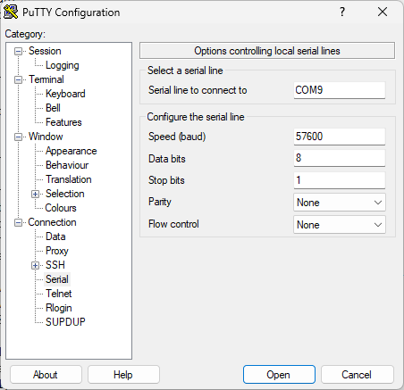 Figure 43. PuTTY Configuration, Serial Connection
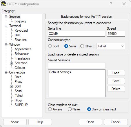 Figure 44. PuTTY Configuration, Session
Select the saved session, and click .
Result
Terminal window opens and diagnostic messages from the Anybus ONE SoM are displayed.