Create your first configuration in Anybus Studio
This example shows how to create a basic Anybus Studio configuration for simulated communication between Modbus RTU and PROFINET on the Evaluation Board.
It includes values you can use directly to create a working configuration.
The configuration is the same as the pre-installed one on Anybus ONE SoM. You can also download it, see Example configuration: download and use.
For detailed information about Anybus Studio configuration, see Configuration workflow.
Before you begin
Create an Anybus Studio account and login. See also Create your Anybus Studio account.
Modbus RTU host interface
Go to Host interface > Modbus RTU.
Parameters
Go to Parameters tab.
Click button Add parameters to Holding Registers to add four Holding registers.
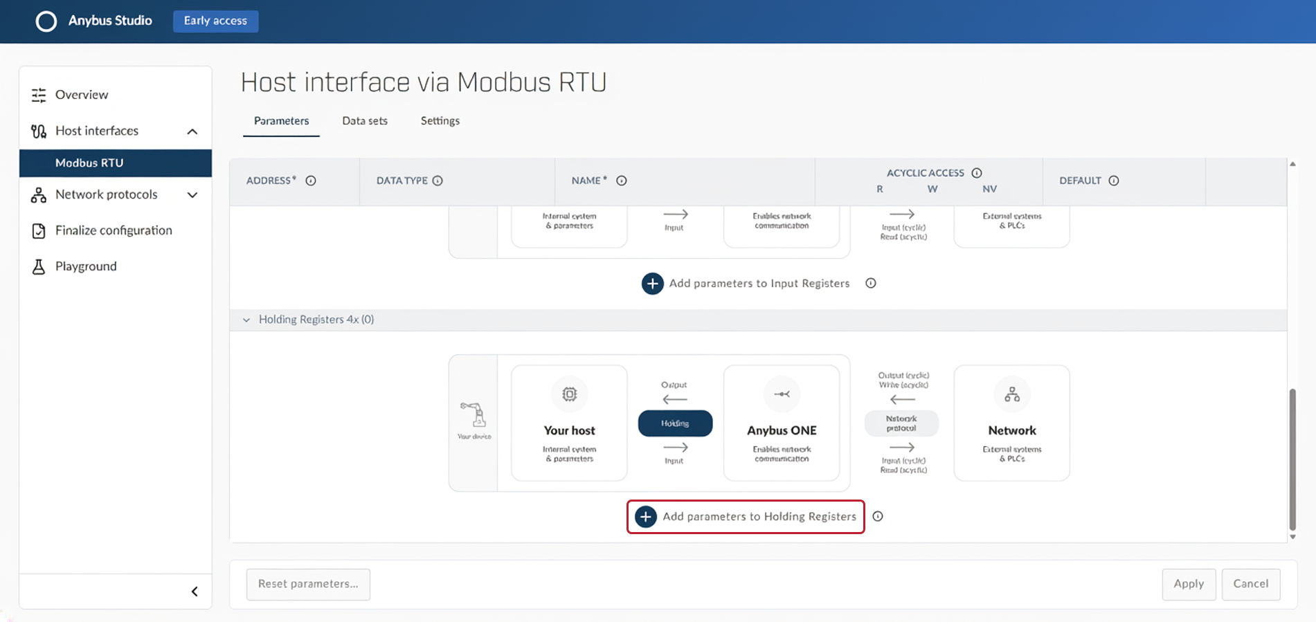
Use these values:
Direction
Address
Name
Data Type
Access
Default
Modbus RTU → PROFINET
0x123
InputParam1
UINT16
R
-
Modbus RTU → PROFINET
0x124
InputParam2
UINT16
R
-
PROFINET → Modbus RTU
0x125
OutputParam1
UINT16
R/W
0x2222
PROFINET → Modbus RTU
0x126
OutputParam2
UINT16
R/W
0x2223
Click button Apply.
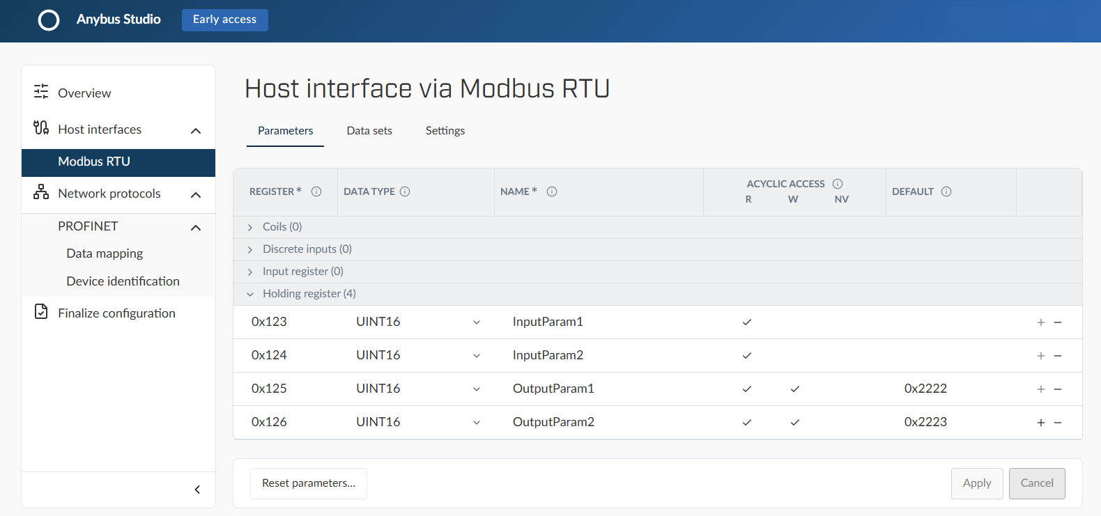
Modbus RTU Parameters example
Figure 25. Modbus RTU Parameters example
Data sets
The host interface needs two data sets: one for input data and one for output data.
Go to Data sets tab.
To create a data set for the InputData, click button New Data Set.
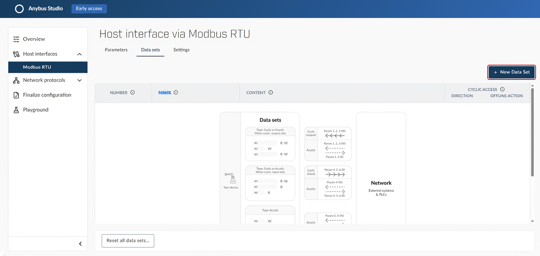 Figure 26. Data sets tab
Enter the following values:
Data set name: InputDataSet
Access type: Cyclic and acyclic
Direction: Input
Add parameters: InputParam1, InputParam2
To save the data set, click button Apply data set.
To create a data set for the OutputData, click button New Data Set.
Enter the following values:
Data set name: OutputDataSet
Access type: Cyclic and acyclic
Direction: Output
Offline action: Use default values
Add parameters: OutParam1, OutputParam2
To save the data set, click button Apply data set.
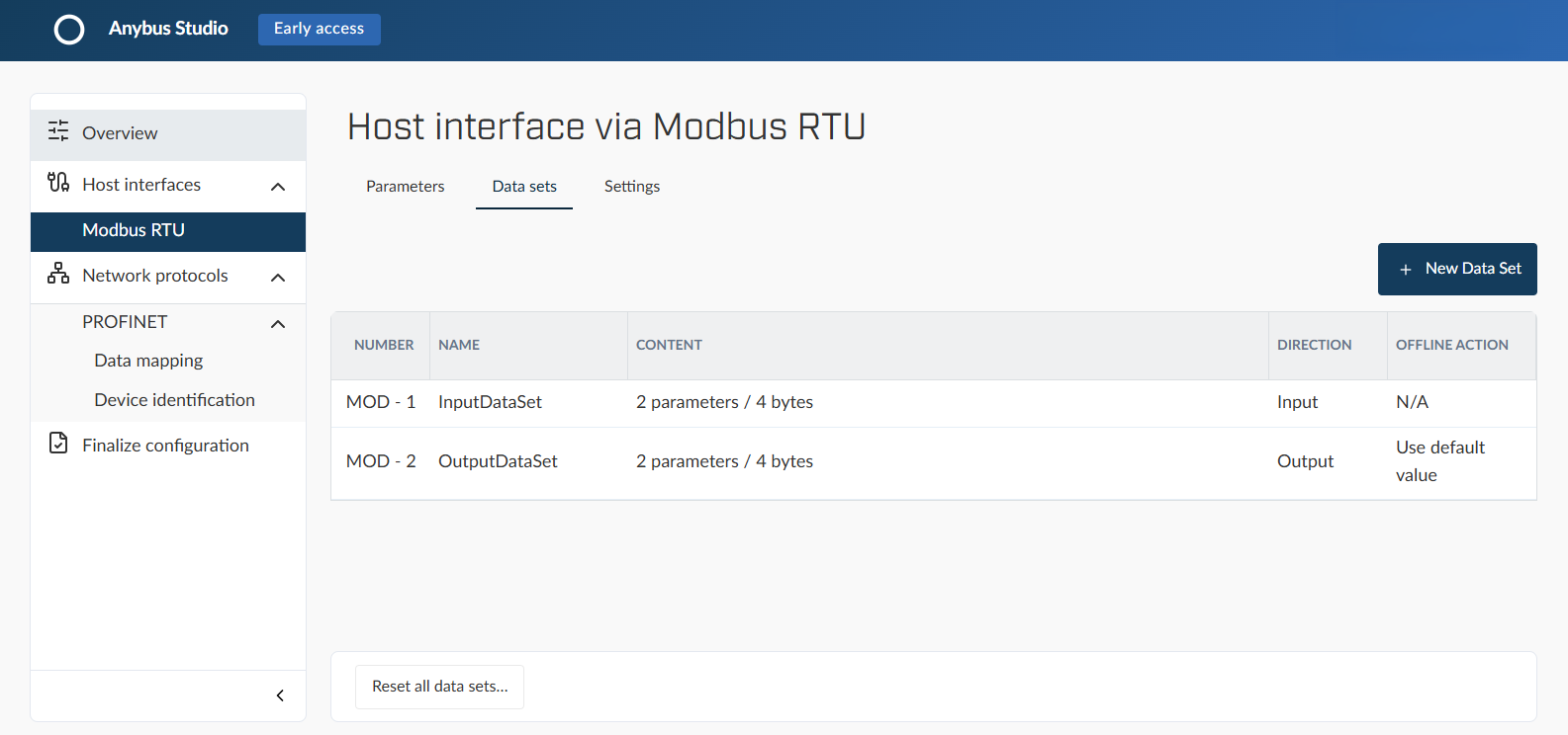
Modbus RTU Data sets example
Figure 27. Modbus RTU Data sets example
Settings
In the Settings tab, configure the communication settings:
Modbus Node ID: 1
Register order: Most significant register first
Bit rate (bps): 115 200
Parity & stop bits: E1 (even parity, 1 stop bit)
Timeout (ms): 500
Retries: 2
Click button Apply.
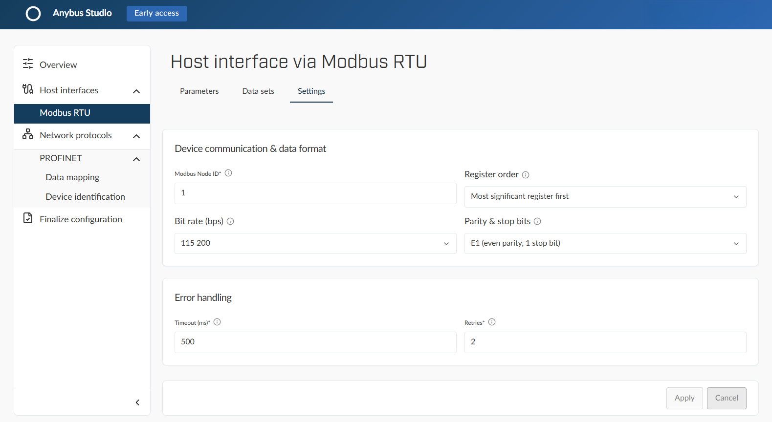
Modbus RTU Settings example
Figure 28. Modbus RTU Settings example
PROFINET data mapping
Go to Network protocols > PROFINET > Data mapping.
Modules
Go to Modules tab.
To add a module, click button Add more modules.
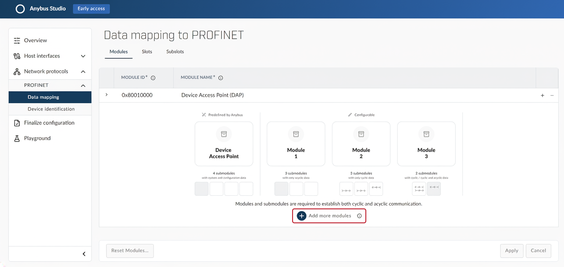 Figure 29. Modules tab
Enter the values for the module and the submodule:
Module ID: 0x00000001
Module name: InputModule
Submodule ID: 0x00000001
Submodule name: InputSubmodule
Cyclic data set, Input: InputDataSet
Cyclic data set, Output: -
Virtual: ✓
Click button + in the module row to repeat step 3 with the following values:
Module ID: 0x00000002
Module name: OutputModule
Submodule ID: 0x00000001
Submodule name: OutputSubmodule
Cyclic data set, Input: -
Cyclic data set, Output: OutputDataSet
Virtual: ✓
Click button Apply.
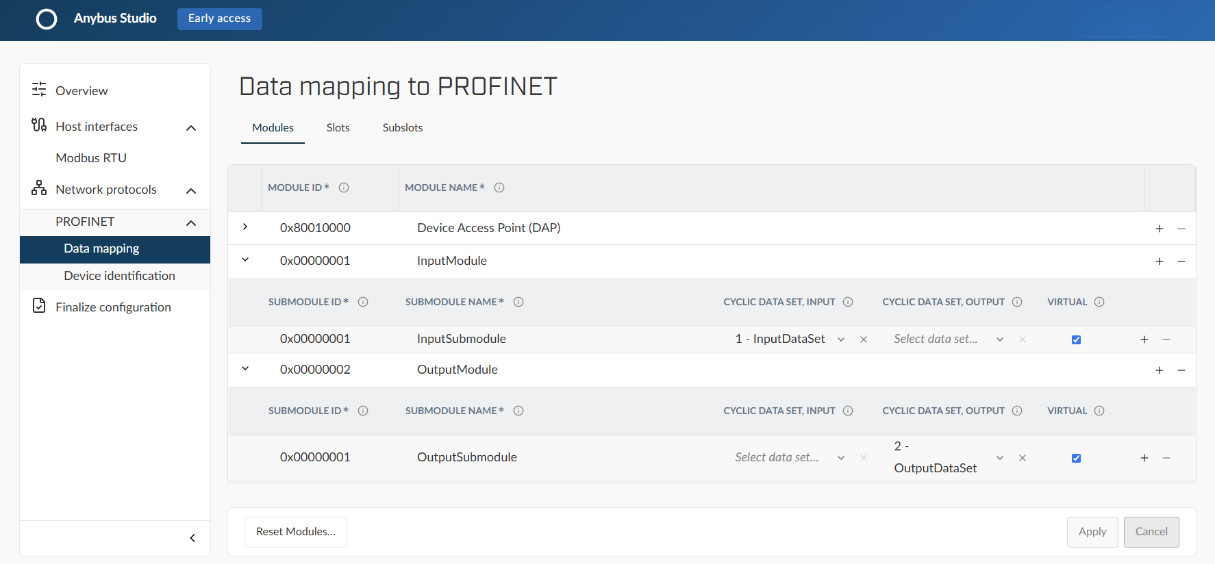
PROFINET Modules example
Figure 30. PROFINET Modules example
The Device Access Point (DAP) module is predefined and cannot be changed. See Device Access Point (DAP).
Slots
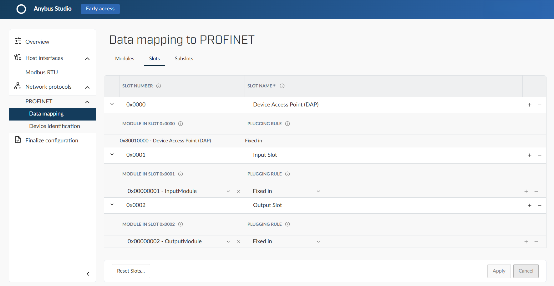
Go to Slots tab.
To add a slot and assign module, click button Add more slots.
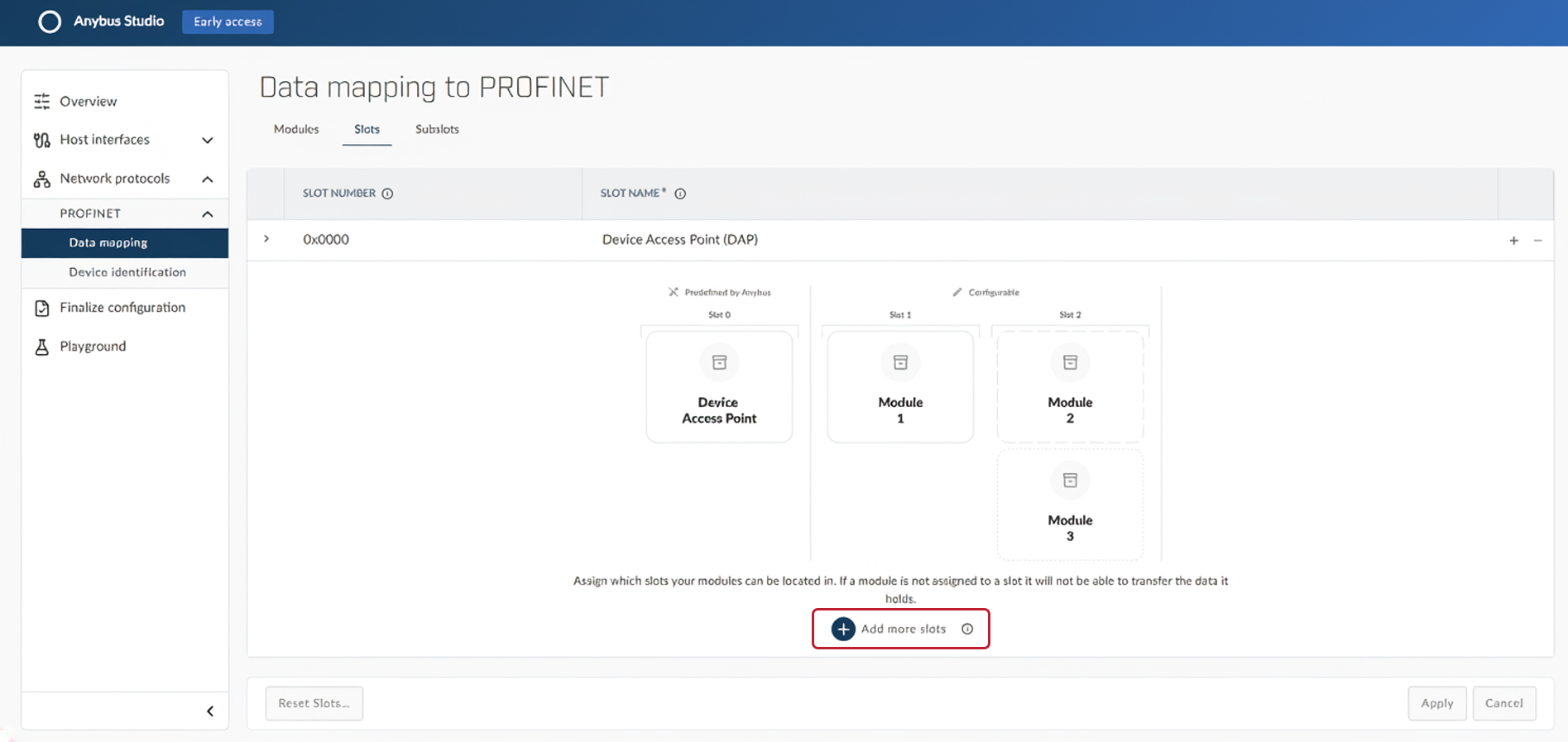 Figure 31. Slots tab
Enter the values for the slot:
Slot number: 0x0001
Name: Input Slot
Module in slot: InputModule
Plugging rule: Fixed in
Click button + and repeat step 3 with the following values:
Slot number: 0x0002
Name: Output Slot
Module in slot: OutputModule
Plugging rule: Fixed in
Click button Apply.
PROFINET Slots example
Figure 32. PROFINET Slots example
The Device Access Point (DAP) module is predefined and cannot be changed. See Device Access Point (DAP).
Subslots
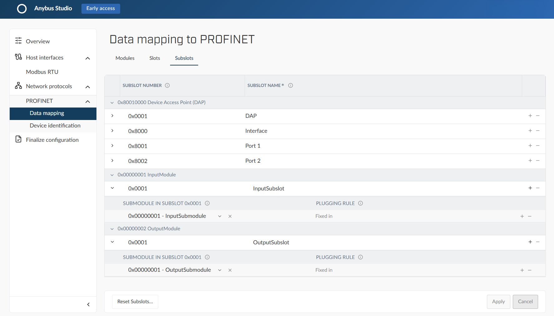
Go to Sublots tab.
Enter the values for the subslots in the InputModule:
Subslot number: 0x0001
Subslot name: InputSubslot
Submodule in subslot: InputSubmodule
Repeat step 2 with the values for the OutputModule:
Subslot number: 0x0001
Subslot name: OutputSubslot
Submodule in subslot: OutputSubmodule
Click button Apply.
PROFINET Subslots example
Figure 33. PROFINET Subslots example
Identification
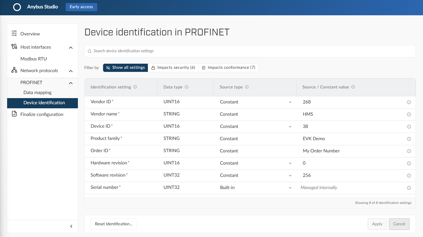
Go to Network protocol > PROFINET > Device identification.
Use default values unless specified:
Identification setting
Data type
Source type
Source / Constant value
Vendor ID
UINT16
Constant
268
Vendor name
STRING
Constant
HMS
Device ID
UINT16
Constant
38
Product family
STRING
Constant
EVK Demo
Order ID
STRING
Constant
My Order Number
Hardware revision
UINT16
Constant
0
Software revision
UINT32
Constant
256
Serial number
UINT32
Built-in
Managed internally
Click button Apply.
PROFINET Identification example
Figure 34. PROFINET Identification example
Result
Two Modbus input parameters mapped to PROFINET input data
Two Modbus output parameters mapped to PROFINET output data
Download configuration files and signing tool
Go to Finalize configuration and download the configuration files.
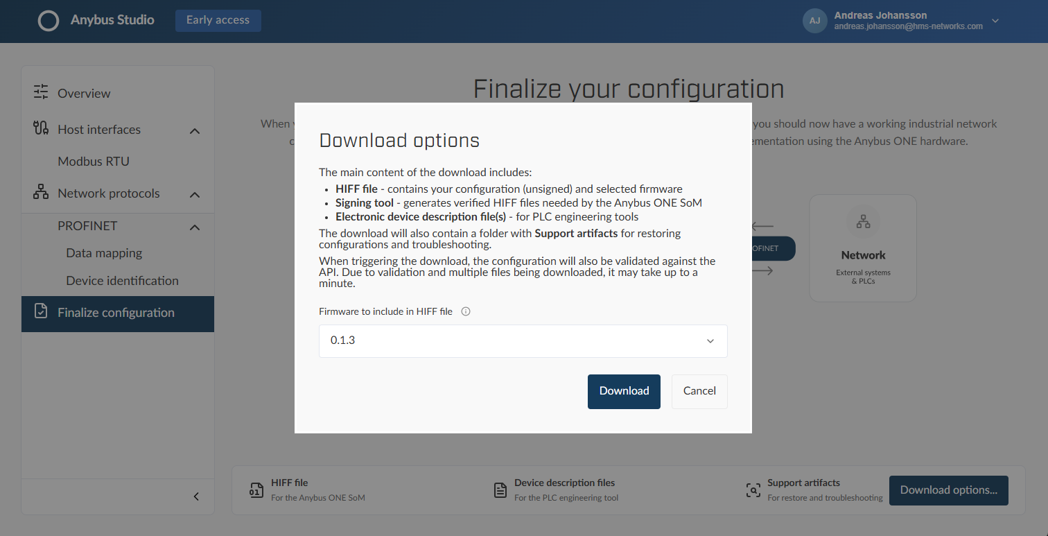 |
The download zip includes the unsigned configuration HIFF file, PROFINET GSDML file, and the Anybus ONE Signing tool.
See also Download configuration files.
Sign configuration HIFF file
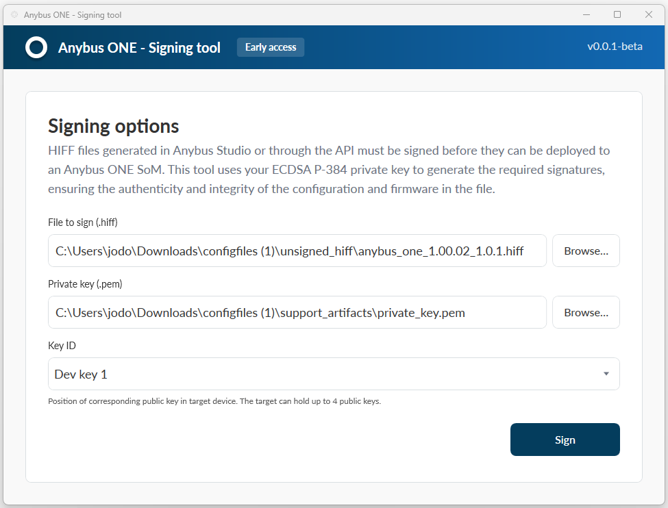
Extract the configuration files (.zip) folder and run the AnybusONE-SigningTool.exe.
The unsigned HIFF file and the private and public key files are selected by default.
The preselected private key is an example key provided with the Anybus Studio output. In a production configuration, this key is replaced with a user-generated private key.
Click .
 |
The signed HIFF file is automatically saved in the extracted configuration files folder.
See also Sign configuration files.
To do next
Install the signed configuration HIFF file on the Evaluation Board SoM. See Install a configuration on the Evaluation Board SoM.