Configure Modbus RTU
Configure the Modbus RTU host interface for your device.
This configuration defines how internal device data is exposed, addressed, and organized over the Modbus RTU interface.
Before you begin
Ensure you have:
Identified the internal device data that must be accessible via Modbus RTU
Defined which data is read‑only, write‑only, or read/write
Determined default values and startup behavior for configurable data
Defined communication requirements for the Modbus RTU serial line
See also Plan your configuration.
Configuration order
Configure Modbus RTU in the following order. Each step builds on the previous one:
Parameters
Data sets
Settings
Add parameters
Parameters represent internal device data and define how it is addressed on the Modbus RTU interface. They are the basic building blocks for both acyclic access and data grouping.
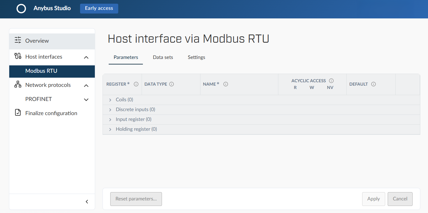
Define parameters in the tab, grouped by Modbus register type.
Parameter definition
For each parameter, define:
Modbus register type: Coils, Discrete inputs, Input registers, or Holding registers
Register address: A unique address in the range 0x0000–0xFFFF
Data type: The data format for the parameter, such as UINT16, UINT32, FLOAT32, or FLOAT64
Name: A descriptive name, visible in engineering tools
Access rights: Read, write, or read/write
Default value: The initial value applied at startup or on factory reset; required for writable parameters
Parameter rules
Register addresses must be unique within each register type
Register type must match the intended access behavior
Default values must be compatible with data type and access rights
Group parameters into data sets
Data sets group parameters into structured data blocks.
They are used to support predictable cyclic communication or logical organization of related data.
Create and manage data sets in the Data sets tab.
Data set definition
For each data set, define:
Data set name: A descriptive name, visible in engineering tools
Access type:
Cyclic, when used for cyclic communication
Acyclic, when used only for logical grouping
Direction: Input or Output, required for cyclic data sets
Parameters: The parameters included in the data set, in a defined order
Data set rules
Parameters may be included in multiple data sets
Cyclic data sets must have a stable and well‑defined parameter order
Data sets should represent consistent and predictable data blocks
Configure serial communication settings
Settings define the low‑level Modbus RTU communication behavior on the serial interface.
They ensure reliable data exchange with Modbus masters.
Configure communication parameters in the Settings tab.
Modbus RTU settings
Define:
Node ID
Bitrate (bps)
Register order
Parity and stop bits
Timeout
Retry behavior
Modbus RTU settings rules
Node IDs must be unique on the Modbus RTU network
Communication settings must match the target network environment
Timeout and retry values must balance reliability and responsiveness
Validate the configuration
Important
The Modbus RTU host interface controls how device data is accessed. Incomplete configuration can result in unavailable or inconsistent data.
For HIFF generation to succeed, ensure the following:
All required parameters are defined and assigned valid register addresses
Register address ranges do not overlap and use the correct register types
Data sets include the intended parameters and consistent data ordering
Modbus RTU communication settings match the target network environment
Result
A valid Modbus RTU host interface configuration ready for HIFF generation.